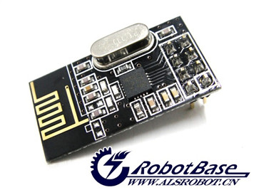
(SKU:RB-03T006)NRF24L01无线数传模块
来自ALSROBOT WiKi
目录 |
产品概述
NRF24L01是一款新型单片射频收发器件,工作于2.4 GHz~2.5 GHz ISM频段。内置频率合成器、功率放大器、晶体振荡器、调制器等功能模块,并融合了增强型ShockBurst技术,其中输出功率和通信频道可通过程序进 行配置。NRF24L01功耗低,在以-6 dBm的功率发射时,工作电流也只有9 mA;接收时,工作电流只有12.3 mA,多种低功率工作模式(掉电模式和空闲模式)使节能设计更方便。
规格参数
- 2Mbit/s速率下接收时的峰值电流12.5mA
- 在2Mbit/s速率下@0dBm输出时的峰值电流11mA
- 掉电模式下的功耗400nA
- 待机模式下的功耗32uA
- 130us 的快速切换和唤醒时间
- 具有片内稳压器oltage regulators
- 可在1.9 to 3.6V低电压工作
- MultiCeiverMT硬件提供同时6个接收机的功能,2Mbit/s 使得高质量的VoIP成为可能
使用方法
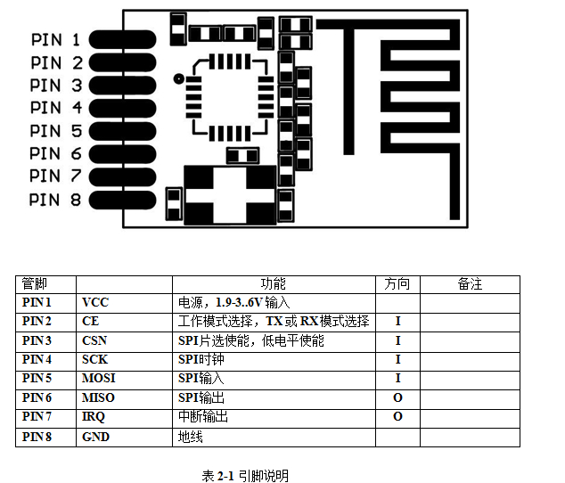
引脚说明
应用例程
1.库文件下载
mirf 库下载地址
2.连接Arduino和NRF2401模块
| NRF2401 | Arduino |
| VCC | 3V3 |
| GND | GND |
| CSN | D7 |
| CE | D8 |
| MOSI | D11 |
| MISO | D12 |
| SCK | D13 |
3.代码下载
发送端代码
/*********************************************************************
**  Device:  nRF24L01+                                              **
**  File:   EF_nRF24L01_TX.c                                        **
**                                                                  **
**                                                                  **
**  Copyright (C) 2011 ElecFraks.                                   **
**  This example code is in the public domain.                      **
**                                                                  **
**  Description:                                                    **
**  This file is a sample code for your reference.                  **
**  It's the v1.0 nRF24L01+ Hardware SPI by arduino                 **
**  Created by ElecFreaks. Robi.W,11 June 2011                      **
**                                                                  **
**  http://www.elecfreaks.com                                       **
**                                                                  **
**   SPI-compatible                                                 **
**   CS - to digital pin 8                                          **
**   CSN - to digital pin 9  (SS pin)                               **
**   MOSI - to digital pin 11 (MOSI pin)                            **
**   MISO - to digital pin 12 (MISO pin)                            **
**   CLK - to digital pin 13 (SCK pin)                              **
*********************************************************************/

#include <SPI.h>
#include "API.h"
#include "nRF24L01.h"

//***************************************************
#define TX_ADR_WIDTH    5   // 5 unsigned chars TX(RX) address width
#define TX_PLOAD_WIDTH  32  // 32 unsigned chars TX payload

unsigned char TX_ADDRESS[TX_ADR_WIDTH]  =
{
  0x34,0x43,0x10,0x10,0x01
}; // Define a static TX address

unsigned char rx_buf[TX_PLOAD_WIDTH] = {0}; // initialize value
unsigned char tx_buf[TX_PLOAD_WIDTH] = {0};
//***************************************************
void setup()
{
  Serial.begin(9600);
  pinMode(CE,  OUTPUT);
  pinMode(CSN, OUTPUT);
  pinMode(IRQ, INPUT);
  SPI.begin();
  delay(50);
  init_io();                        // Initialize IO port
  unsigned char sstatus=SPI_Read(STATUS);
  Serial.println("*******************TX_Mode Start****************************");
  Serial.print("status = ");
  Serial.println(sstatus,HEX);     // There is read the mode’s status register, the default value should be ‘E’
  TX_Mode();                       // set TX mode
}

void loop()
{
  int k = 0;
  for(;;)
  {
    for(int i=0; i<32; i++)
        tx_buf[i] = k++;
    unsigned char sstatus = SPI_Read(STATUS);                   // read register STATUS's value
    if(sstatus&TX_DS)                                           // if receive data ready (TX_DS) interrupt
    {
      SPI_RW_Reg(FLUSH_TX,0);
      SPI_Write_Buf(WR_TX_PLOAD,tx_buf,TX_PLOAD_WIDTH);       // write playload to TX_FIFO
    }
    if(sstatus&MAX_RT)                                         // if receive data ready (MAX_RT) interrupt, this is retransmit than  SETUP_RETR
    {
      SPI_RW_Reg(FLUSH_TX,0);
      SPI_Write_Buf(WR_TX_PLOAD,tx_buf,TX_PLOAD_WIDTH);      // disable standy-mode
    }
    SPI_RW_Reg(WRITE_REG+STATUS,sstatus);                     // clear RX_DR or TX_DS or MAX_RT interrupt flag
    delay(1000);
  }
}

//**************************************************
// Function: init_io();
// Description:
// flash led one time,chip enable(ready to TX or RX Mode),
// Spi disable,Spi clock line init high
//**************************************************
void init_io(void)
{
  digitalWrite(IRQ, 0);
  digitalWrite(CE, 0);			// chip enable
  digitalWrite(CSN, 1);                 // Spi disable
}

/************************************************************************
**   * Function: SPI_RW();
 *
 * Description:
 * Writes one unsigned char to nRF24L01, and return the unsigned char read
 * from nRF24L01 during write, according to SPI protocol
************************************************************************/
unsigned char SPI_RW(unsigned char Byte)
{
  return SPI.transfer(Byte);
}

/**************************************************/

/**************************************************
 * Function: SPI_RW_Reg();
 *
 * Description:
 * Writes value 'value' to register 'reg'
/**************************************************/
unsigned char SPI_RW_Reg(unsigned char reg, unsigned char value)
{
  unsigned char status;

  digitalWrite(CSN, 0);                   // CSN low, init SPI transaction
  SPI_RW(reg);                            // select register
  SPI_RW(value);                          // ..and write value to it..
  digitalWrite(CSN, 1);                   // CSN high again

  return(status);                   // return nRF24L01 status unsigned char
}
/**************************************************/

/**************************************************
 * Function: SPI_Read();
 *
 * Description:
 * Read one unsigned char from nRF24L01 register, 'reg'
/**************************************************/
unsigned char SPI_Read(unsigned char reg)
{
  unsigned char reg_val;

  digitalWrite(CSN, 0);                // CSN low, initialize SPI communication...
  SPI_RW(reg);                         // Select register to read from..
  reg_val = SPI_RW(0);                 // ..then read register value
  digitalWrite(CSN, 1);                // CSN high, terminate SPI communication

  return(reg_val);                     // return register value
}
/**************************************************/

/**************************************************
 * Function: SPI_Read_Buf();
 *
 * Description:
 * Reads 'unsigned chars' #of unsigned chars from register 'reg'
 * Typically used to read RX payload, Rx/Tx address
/**************************************************/
unsigned char SPI_Read_Buf(unsigned char reg, unsigned char *pBuf, unsigned char bytes)
{
  unsigned char sstatus,i;

  digitalWrite(CSN, 0);                   // Set CSN low, init SPI tranaction
  sstatus = SPI_RW(reg);       	    // Select register to write to and read status unsigned char

  for(i=0;i<bytes;i++)
  {
    pBuf[i] = SPI_RW(0);    // Perform SPI_RW to read unsigned char from nRF24L01
  }

  digitalWrite(CSN, 1);                   // Set CSN high again

  return(sstatus);                  // return nRF24L01 status unsigned char
}
/**************************************************/

/**************************************************
 * Function: SPI_Write_Buf();
 *
 * Description:
 * Writes contents of buffer '*pBuf' to nRF24L01
 * Typically used to write TX payload, Rx/Tx address
/**************************************************/
unsigned char SPI_Write_Buf(unsigned char reg, unsigned char *pBuf, unsigned char bytes)
{
  unsigned char sstatus,i;

  digitalWrite(CSN, 0);                   // Set CSN low, init SPI tranaction
  sstatus = SPI_RW(reg);             // Select register to write to and read status unsigned char
  for(i=0;i<bytes; i++)             // then write all unsigned char in buffer(*pBuf)
  {
    SPI_RW(*pBuf++);
  }
  digitalWrite(CSN, 1);                   // Set CSN high again
  return(sstatus);                  // return nRF24L01 status unsigned char
}
/**************************************************/

/**************************************************
 * Function: TX_Mode();
 *
 * Description:
 * This function initializes one nRF24L01 device to
 * TX mode, set TX address, set RX address for auto.ack,
 * fill TX payload, select RF channel, datarate & TX pwr.
 * PWR_UP is set, CRC(2 unsigned chars) is enabled, & PRIM:TX.
 *
 * ToDo: One high pulse(>10us) on CE will now send this
 * packet and expext an acknowledgment from the RX device.
 **************************************************/
void TX_Mode(void)
{
  digitalWrite(CE, 0);

  SPI_Write_Buf(WRITE_REG + TX_ADDR, TX_ADDRESS, TX_ADR_WIDTH);    // Writes TX_Address to nRF24L01
  SPI_Write_Buf(WRITE_REG + RX_ADDR_P0, TX_ADDRESS, TX_ADR_WIDTH); // RX_Addr0 same as TX_Adr for Auto.Ack

  SPI_RW_Reg(WRITE_REG + EN_AA, 0x01);      // Enable Auto.Ack:Pipe0
  SPI_RW_Reg(WRITE_REG + EN_RXADDR, 0x01);  // Enable Pipe0
  SPI_RW_Reg(WRITE_REG + SETUP_RETR, 0x1a); // 500us + 86us, 10 retrans...
  SPI_RW_Reg(WRITE_REG + RF_CH, 40);        // Select RF channel 40
  SPI_RW_Reg(WRITE_REG + RF_SETUP, 0x07);   // TX_PWR:0dBm, Datarate:2Mbps, LNA:HCURR
  SPI_RW_Reg(WRITE_REG + CONFIG, 0x0e);     // Set PWR_UP bit, enable CRC(2 unsigned chars) & Prim:TX. MAX_RT & TX_DS enabled..
  SPI_Write_Buf(WR_TX_PLOAD,tx_buf,TX_PLOAD_WIDTH);

  digitalWrite(CE, 1);
}
接收端代码:
/*********************************************************************
**  Device:  nRF24L01+                                              **
**  File:   EF_nRF24L01_RX.c                                        **
**                                                                  **
**                                                                  **
**  Copyright (C) 2011 ElecFraks.                                   **
**  This example code is in the public domain.                      **
**                                                                  **
**  Description:                                                    **
**  This file is a sample code for your reference.                  **
**  It's the v1.0 nRF24L01+ Hardware SPI by arduino                 **
**  Created by ElecFreaks. Robi.W,11 June 2011                      **
**                                                                  **
**  http://www.elecfreaks.com                                       **
**                                                                  **
**   SPI-compatible                                                 **
**   CS - to digital pin 8                                          **
**   CSN - to digital pin 9  (SS pin)                               **
**   MOSI - to digital pin 11 (MOSI pin)                            **
**   MISO - to digital pin 12 (MISO pin)                            **
**   CLK - to digital pin 13 (SCK pin)                              **
*********************************************************************/


#include <SPI.h>
#include "API.h"
#include "nRF24L01.h"

//***************************************************
#define TX_ADR_WIDTH    5   // 5 unsigned chars TX(RX) address width
#define TX_PLOAD_WIDTH  32  // 32 unsigned chars TX payload

unsigned char TX_ADDRESS[TX_ADR_WIDTH]  =
{
  0x34,0x43,0x10,0x10,0x01
}; // Define a static TX address

unsigned char rx_buf[TX_PLOAD_WIDTH] = {0}; // initialize value
unsigned char tx_buf[TX_PLOAD_WIDTH] = {0};
//***************************************************
void setup()
{
  Serial.begin(9600);
  pinMode(CE,  OUTPUT);
  pinMode(CSN, OUTPUT);
  pinMode(IRQ, INPUT);
  SPI.begin();
  delay(50);
  init_io();                        // Initialize IO port
  unsigned char sstatus=SPI_Read(STATUS);
  Serial.println("*******************RX_Mode Start****************************");
  Serial.print("status = ");
  Serial.println(sstatus,HEX);     // There is read the mode’s status register, the default value should be ‘E’
  RX_Mode();                        // set RX mode
}

void loop()
{
  for(;;)
  {
    unsigned char status = SPI_Read(STATUS);                         // read register STATUS's value
    if(status&RX_DR)                                                 // if receive data ready (TX_DS) interrupt
    {
      SPI_Read_Buf(RD_RX_PLOAD, rx_buf, TX_PLOAD_WIDTH);             // read playload to rx_buf
      SPI_RW_Reg(FLUSH_RX,0);                                        // clear RX_FIFO
      for(int i=0; i<32; i++)
      {
          Serial.print(" ");
          Serial.print(rx_buf[i],HEX);                              // print rx_buf
      }
      Serial.println(" ");
    }
    SPI_RW_Reg(WRITE_REG+STATUS,status);                             // clear RX_DR or TX_DS or MAX_RT interrupt flag
    delay(1000);
  }
}

//**************************************************
// Function: init_io();
// Description:
// flash led one time,chip enable(ready to TX or RX Mode),
// Spi disable,Spi clock line init high
//**************************************************
void init_io(void)
{
  digitalWrite(IRQ, 0);
  digitalWrite(CE, 0);			// chip enable
  digitalWrite(CSN, 1);                 // Spi disable
}

/************************************************************************
**   * Function: SPI_RW();
 *
 * Description:
 * Writes one unsigned char to nRF24L01, and return the unsigned char read
 * from nRF24L01 during write, according to SPI protocol
************************************************************************/
unsigned char SPI_RW(unsigned char Byte)
{
  return SPI.transfer(Byte);
}

/**************************************************/

/**************************************************
 * Function: SPI_RW_Reg();
 *
 * Description:
 * Writes value 'value' to register 'reg'
/**************************************************/
unsigned char SPI_RW_Reg(unsigned char reg, unsigned char value)
{
  unsigned char status;

  digitalWrite(CSN, 0);                   // CSN low, init SPI transaction
  SPI_RW(reg);                            // select register
  SPI_RW(value);                          // ..and write value to it..
  digitalWrite(CSN, 1);                   // CSN high again

  return(status);                   // return nRF24L01 status unsigned char
}
/**************************************************/

/**************************************************
 * Function: SPI_Read();
 *
 * Description:
 * Read one unsigned char from nRF24L01 register, 'reg'
/**************************************************/
unsigned char SPI_Read(unsigned char reg)
{
  unsigned char reg_val;

  digitalWrite(CSN, 0);                // CSN low, initialize SPI communication...
  SPI_RW(reg);                         // Select register to read from..
  reg_val = SPI_RW(0);                 // ..then read register value
  digitalWrite(CSN, 1);                // CSN high, terminate SPI communication

  return(reg_val);                     // return register value
}
/**************************************************/

/**************************************************
 * Function: SPI_Read_Buf();
 *
 * Description:
 * Reads 'unsigned chars' #of unsigned chars from register 'reg'
 * Typically used to read RX payload, Rx/Tx address
/**************************************************/
unsigned char SPI_Read_Buf(unsigned char reg, unsigned char *pBuf, unsigned char bytes)
{
  unsigned char sstatus,i;

  digitalWrite(CSN, 0);                   // Set CSN low, init SPI tranaction
  sstatus = SPI_RW(reg);       	    // Select register to write to and read status unsigned char

  for(i=0;i<bytes;i++)
  {
    pBuf[i] = SPI_RW(0);    // Perform SPI_RW to read unsigned char from nRF24L01
  }

  digitalWrite(CSN, 1);                   // Set CSN high again

  return(sstatus);                  // return nRF24L01 status unsigned char
}
/**************************************************/

/**************************************************
 * Function: SPI_Write_Buf();
 *
 * Description:
 * Writes contents of buffer '*pBuf' to nRF24L01
 * Typically used to write TX payload, Rx/Tx address
/**************************************************/
unsigned char SPI_Write_Buf(unsigned char reg, unsigned char *pBuf, unsigned char bytes)
{
  unsigned char sstatus,i;

  digitalWrite(CSN, 0);                   // Set CSN low, init SPI tranaction
  sstatus = SPI_RW(reg);             // Select register to write to and read status unsigned char
  for(i=0;i<bytes; i++)             // then write all unsigned char in buffer(*pBuf)
  {
    SPI_RW(*pBuf++);
  }
  digitalWrite(CSN, 1);                   // Set CSN high again
  return(sstatus);                  // return nRF24L01 status unsigned char
}
/**************************************************/

void RX_Mode(void)
{
  digitalWrite(CE, 0);

  SPI_Write_Buf(WRITE_REG + RX_ADDR_P0, TX_ADDRESS, TX_ADR_WIDTH); // Use the same address on the RX device as the TX device
  SPI_RW_Reg(WRITE_REG + EN_AA, 0x01);      // Enable Auto.Ack:Pipe0
  SPI_RW_Reg(WRITE_REG + EN_RXADDR, 0x01);  // Enable Pipe0
  SPI_RW_Reg(WRITE_REG + RF_CH, 40);        // Select RF channel 40
  SPI_RW_Reg(WRITE_REG + RX_PW_P0, TX_PLOAD_WIDTH); // Select same RX payload width as TX Payload width
  SPI_RW_Reg(WRITE_REG + RF_SETUP, 0x07);   // TX_PWR:0dBm, Datarate:2Mbps, LNA:HCURR
  SPI_RW_Reg(WRITE_REG + CONFIG, 0x0f);     // Set PWR_UP bit, enable CRC(2 unsigned chars) & Prim:RX. RX_DR enabled..
  digitalWrite(CE, 1);                             // Set CE pin high to enable RX device
  //  This device is now ready to receive one packet of 16 unsigned chars payload from a TX device sending to address
  //  '3443101001', with auto acknowledgment, retransmit count of 10, RF channel 40 and datarate = 2Mbps.
}


